The bare diagram
When you start Structorizer or create a new diagram (via button  or key <Ctrl><N>), then you will be presented an empty diagram with dummy name "???" (the red triangle just flags the related Analyser hint in the bottom report list): or key <Ctrl><N>), then you will be presented an empty diagram with dummy name "???" (the red triangle just flags the related Analyser hint in the bottom report list):
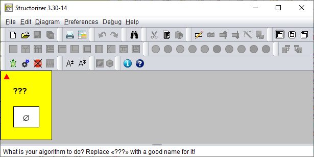
Double-click the question marks and fill in a sensible name in the upper text field superscribed with "Diagram name / function signature" of the element editor that will pop up.
- The name should represent the aim of your algorithm.
- The name should be an "identifier", i.e.:
- The name should not contain spaces: THIS IS NOT A GOOD ALGORITHM NAME.
- If the name is to consist of several words, you may fill the gaps between the words with underscores: THE_ALGORITHM_NAME_SHOULD_BE_CONTIGUOUS.
- Ideally, the algorithm name should start with a letter and contain only letters, digits and underscores (identifier syntax).
Also make sure to fill in the lower text field (superscribed "Comment") with a description of what the algorithm is good for and how to use it.
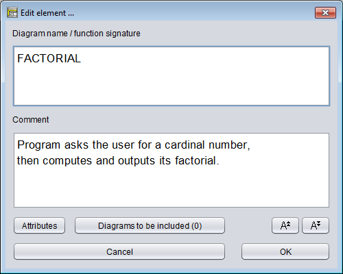
The framing (or root) element of a Nassi-Shneiderman diagram represents either a program, a (callable) subroutine, or an includable diagram (also see Type setting).
- A program or main means a standalone algorithm (an application) as being executable as a process on the operating system level. It usually communicates with the user via input and output instructions.
- A subroutine typically means a parameterised algorithm that can be used to perform some subordinate task within a program or another routine, e.g. to calculate the area of a circle with given radius, the volume of a cuboid, or the average (mean value) of a given list of numbers. Or you might want to draw a certain figure with the turtle several times at different places in the Turtleizer tool. Subroutines usually cannot access variables outside their scope but are provided with the values they need via parameters (on calling). On the other hand, they possibly return a result value to the calling level. Whereas subroutines like calculating the sine of an angle or the square root of a number are already built in (as is e.g. the rotation of the turtle by some degrees in Turtleizer), more complex subtasks may arise on decomposing an algorithmic problem. Then you will usually find it helpful to define your own subroutines, in particular if you have to perform them several times with differing parameter values. And you should decompose an algrithm that grows too large to keep the overview (structogams are not meant to rise to the size of a soccer field!). Depending on whether subroutines return a value or not, they are usually subdivided into
- procedures, not returning a value (and rather effectuating some impact to the environment);
- functions, supposed to return a result (usually without further impacts or side-effects).
- An includable diagram (as introduced with release 3.27) is typically a collection of constant definitions, type definitions, and declarations of variables, which are to be shared e.g. among a main diagram and some of its subroutine diagrams. In order to get hold of the defined data, a diagram must include the includable diagram by adding it to its include list, which is accessible via the button "Diagrams to be included" near the bottom of the editor (see screenshot above). In versions prior to release 3.29 the list had been editable in a faintly yellowish upper text field superscribed "Diagrams to be included" above the "Diagram name / function signature" text area.
Structorizer allows you to distinguish visually whether a created diagram is meant to be a program, a subroutine, or an includable diagram — they differ in the shape of the surrounding box:
- A program diagram has rectangular shape,
- the corners of a subroutine diagram will be rounded,
- an includable diagram has two bevelled corners.
How to set the type of the diagram?
Just select the appropriate one of the menu items "Diagram › Type › Main" / "Diagram › Type › Sub" / "Diagram › Type › Includable" (see screenshot) or one of the toolbar buttons boxed red in the screenshot (cf Settings/Type).
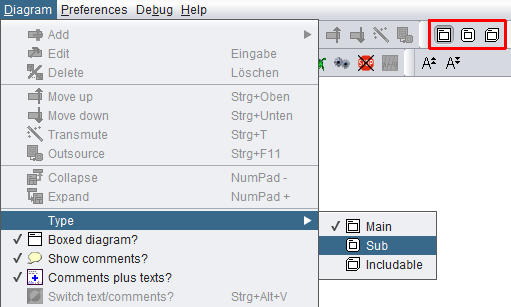
When you start with a new diagram, it will initially be of the program type. The following images show you the computation of the factorial both as a program (left) and as a function (right). Note that the assignment to variable result is one of three supported value return mechanisms (see last paragraph below).
In order to allow you a subroutine simulation at the top level (i.e. without calling context), the Executor will pop up an input dialog for every function parameter before the execution and an output dialog showing the computed result on termination. (But this is only the case while you execute a subroutine diagram at top level.)
Diagram header
If the diagram is a program (main) or an includable diagram then the text field is supposed to contain just its name. A program name should be an identifier as described above, i.e. a word consisting of letters, digits, and underscores, beginning with a letter or underscore. It should not contain blanks.
A subroutine header, however, is supposed to contain more information than just the name. The subroutine name (an identifier as described above) is to be followed by a parameter list. A parameter list — in its simplest form — is a pair of parentheses containing a series of parameter names, separated by comma or semicolon (see example above).
- It may have Pascal syntax (where each parameter name is followed by a colon and a type name. The parameter specifications are to be separated by semicolons. If several parameters are of the same type, they may be grouped to a comma-separated list of their names, followed by the common colon and type name; note the semicolon between parameter groups! The result type — if any — follows the parameter list, separated from it by a colon), e.g.
functionName(var1, var2: Cardinal; var3: Double): Double
- Alternatively, it may have C/Java syntax (where the name of any parameter follows its type name; all parameter specifications are separated by commas, a grouping of parameters of the same type is not possible, semicolons are not allowed; the result type precedes the function name), e.g.
double functionName(int var1, int var2, double var3)
- It may also be expressed in BASIC-like syntax (very similar to Pascal syntax, except that the keyword as is to be used instead of the colon and neither parameter grouping nor semicolons are allowed) , e.g.:
functionName(var1 as Integer, var2 as Integer, var3 as Double) as Double
All three forms will be accepted by Structorizer and converted into proper function headers on code export if possible.
Structorizer allows so called overloading of subroutines, i.e. several subroutines may have the same name, provided their parameter numbers differ. Since typing of parameters (and variables in general) is neither mandatory nor even consistently forced if data types happen to be specified, Structorizer does not attempt to distinguish argument lists by argument types. Only the argument counts make a significant difference.
Be aware, however, that parameter order matters: This first argument value of a call is always assigned to the first parameter variable of the matching subroutine and so forth (argument assignment by position).
Since version 3.29-05, Structorizer supports optional parameters, as many programming languages (e.g. C++, C#, Python, VisualBasic, Delphi etc.) do. This means that a subroutine may be called with a shortened argument list, the call may omit some right-most arguments, in which case default values replace the missing arguments. If you want to make use of this opportunity you must specify the default values in the subroutine header — simply append an equality sign with a constant value (a value literal) to the parameters you want to make optional, e.g.:
double func1(int var1, int var2 = 3, double var3 = -8.7)
func2(var1, var2: Cardinal; var3: Double = 2.6E9): Double
It is important, however, that default values must be placed contiguously from right to left. Or, in other words, the first parameter you make optional requires that all subsequent parameters be optional as well. Likewise, a call may only omit a number of arguments from the end of the list, not inbetween (there is no cherry picking). The range of possible argument numbers for the call is shown in the symbolic signatures of the diagrams (as presented in the Arranger Index) — for the two demo functions above this would look like this (the parentheses contain the minimum and maximum argument numbers separated by a hyphen):
func1(1-3)
func2(2-3)
Return mechanisms
In order to return a value from a function diagram, you have the choice among three possible mechanisms supported by Structorizer (i.e. both execution and code export):
- Assign the value to a variable named exactly like the subroutine (like in Pascal; in the above example you might modify the last line to: factorial <- fact);
- Assign the value to a variable named "RESULT", "Result", or "result" (as shown in the example above);
- Add a return instruction (like in C, Java, and the like; modify the last line in the above example to: return fact).
The first two of the opportunities allow to override a provisionally assigned value by subsequent instructions such that just the last performed assignment to the function name or result variable will be the final result, whereas a return instruction will immediately force the termination of the subroutine with the attached result wherever it may occur and be executed.
You should not employ more than one of the three result mechanisms described above within the same diagram, otherwise the result is ambiguous and may not be what you expected it to be.
Note that mechanism 1 will cause Analyser complaints if option "Check that the program / sub name is not equal to any other identifier" is enabled in the Analyser Preferences.
Subroutine creation aids
Structorizer offers some helpful tools to facilitate the creation of suited subroutines along a top-down design paradigm:
- Menu item "Edit › Edit Subroutine" (to be applied on a selected CALL element; also available via the context menu or key binding <Ctrl><Enter>)
creates a subroutine diagram with matching interface if it hadn't existed before and opens it for editing.
- Menu item "Diagram › Outsource" (to be applied on a selected element sequence; also available via the context menu or key binding <Ctrl><F11>)
extracts the selected elements from the current diagram and converts the sequence into a subroutine, infering the required arguments and return values and replacing the sequence by a matching CALL element.
Includable diagrams (introduced with release 3.27)
The third diagram type differs from the types above in two important aspects:
- it shares its defined types, constants, and declared variables with all diagrams including it;
- it is executed at most once — from the first executed diagram that holds it in its include list.
Includable diagrams were introduced in order to:
- cope with code import and export of some source languages, where global definitions, include files etc. are a common feature;
- be able to introduce compound types (aka record, struct), which require a definition possibly having to be shared between a calling diagram and a called diagram if the argument list happens to contain a parameter of such a record type.
Whereas it is okay to share types and constants, it is not recommendable (though possible) to share variables this way. Indeed, the use of shared (global) variables should be avoided on algorithm design, because
- it hides the flow of data (if accessed bypassing the parameter lists),
- it bears always the risk of unwanted interference,
- it drastically limits the general usability of the algorithm.
Example of an includable diagram, defining a constant, providing a shareable variable and writing a text once (only on the first include within a program execution):
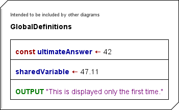
Ideally, the diagrams to be included (the "includable diagrams") should only contain constant definitions and type definitions, and — if inevitable — variable declarations, variable initializations, and the like. The following example demonstrates that the constant ultimateAnswer defined in diagram "GlobalDefinitions" is recognized and therefore highlighted in the importing diagram "ImportCallDemo" as if it were introduced by the importing diagram itself (which is not the case because the preceding assignment "ultimateAnswer <- 3" is disabled — if it were enabled you would be warned of an illegal attempt to modify a constant).
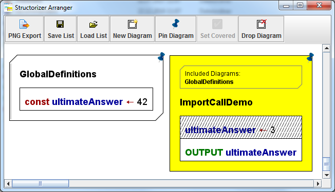
The right diagram displays the list of the names of diagrams to be included. The list is positioned above the program name or function signature and is surrounded by a bevelled box, which reminds the shape of an includable diagram.
The list of diagrams to be included is configured via the element editor of the including (dependent) diagram. Since release 3.29 you will find a button "Diagrams to be included (#)" at the bottom of the element editor. You may open the editor pane for the include list by pressing this button. Letting the mouse hover over the button provokes a tooltip displaying all include names:

The editor pane that pops up on pressing the button allows you to configure which Includable diagrams are actually to be included by the current program / routine / includable diagram. It contains a simple text area where you may write or modify the names of the diagrams to be included (separated by newline or comma). Above the text area, a pull down choice list and a simple "Add" button occur if Includable diagrams are available in Arranger for selection:
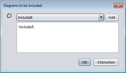
So you may choose the name of an available Includable and add it to the text by a click on the "Add" button. In order to remove an entry no longer wanted just delete it from the text area. If the entry you want to add is already in the text box then the "Add" button will not have an effect.
On this occasion it should be mentioned that included diagrams may (of course) in turn include other includable diagrams. This may even be necessary to ensure their order of execution in case of dependencies (if a diagram C includes A and B, and A must be read before B then B should in turn include A rather than rely on the order in the include list of C). But there must never be a cyclic inclusion (e.g. diagram A includes diagram B, which in turn includes diagram A)! Analyser and Executor do their best to detect and avert such a cyclic inclusion, however.
With version 3.30-15, Structorizer extends the service to facilitate the editing or creation of referenced diagrams from called subroutines to included diagrams: When you select the frame of a diagram that has a non-empty include list then the menu items "Edit subroutine ..." in the "Edit" andthe context menu alter their apperance and allow to summon an included diagram into a Structorizer editing context.
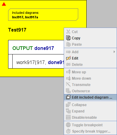
If the include list of the selected diagram contains more than one entry then you will obtain a request to choose among the listed Includables:
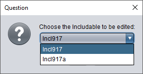
If the selected Includable name is ambiguous (several diagrams with same name in Arranger and group membership does not help to disambiguate them) then you will again be requested to choose among the existing diagrams (this time the choice list will show the file paths as well, because the name alone wouldn't help to tell them from each other).
Conversely, if there is no matching diagram in the pool then you will be asked whether you want to create the missing diagram:
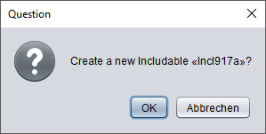
After having confirmed that, an Includable with the chosen name will be created and placed in Arranger. If the including ("parent") diagram had not been residing in the Arranger it will be pushed there as well, possibly a new arrangement group will be formed around both diagrams (if the parent diagram hadn't been member of some group yet). An additional instance of Structorizer holding the new diagram will plop up:

The new Structorizer instance will gain the focus.
Attribute Inspector
There is an "Attributes" button below the comment field in the element editor for Program/Sub/Includable, which opens an "Attribute Inspector" dialog where you may inspect more meta information about the diagram and set or modify some of them. For a new diagram, it might look like this:
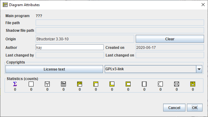
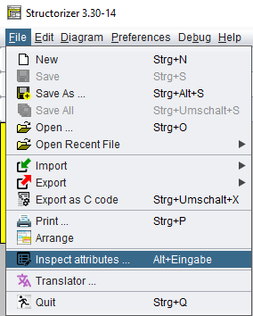
You may open this dialog also via the file menu ("File › Inspect attributes...") or with key combination <Alt><Enter> from the working area:
Since version 3.28-08, you may also activate the "Attribute Inspector" for any diagram located in the Arranger via the context menu of the Arranger Index (provided a diagram node is selected) or the Arranger itself.
The "Attribute Inspector" allows you to have a look at the meta information about the diagram, including paths, author, creation and modification dates, stored copyright information etc. It also shows you the counts of contained elements per type and it may present the differing associated keywords if the diagram was loaded without automatic keyword refactoring (as to be enabled in the Import Preferences):
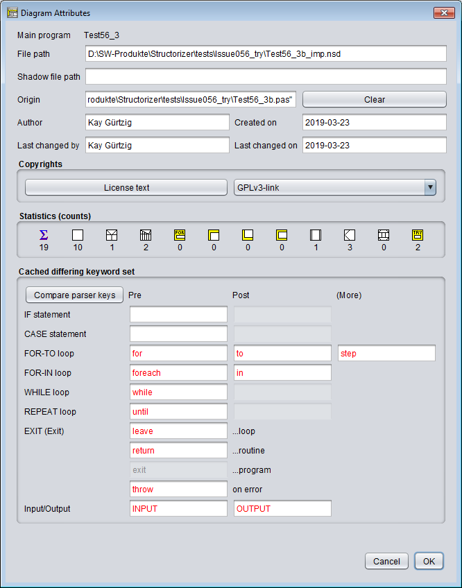
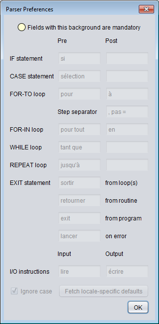
By pressing the button "Compare parser keys" in such a case you may additionally open the Parser Preferences window in read-only mode such that you can compare the current preferences with the ones attached to the diagram (particularly those marked red in the Attribute Inspector):
|

